What do we do with wires class? CONNECT THEM, that’s right. There are a few ways of connecting wires. Certain ways are better depending on the use of that wire. This thread will discuss some of those methods, with emphasis on the two most correct ways, soldering and crimping.
"Strip back the insulation and twist them up"
 DO NOT DO THIS
This is a very good way to make sparks and ruin the CD player you just spent all your rent money on. Twisting up wires is a poor electrical connection with excessive resistance and can short to any of the 11 or so other deck wires or to the chassis. The connection is also mechanically poor due to the fact that it may be pulled or vibrate loose at any second.
"Strip back the insulation, twist, and electrical tape"
 DO NOT DO THIS
Although this adds a little insulation to the above first option, it often falls off the second you put the deck in. This then suffers from all the negatives of the 1st connection.
"Wire Nuts"
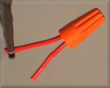 Questionable for Automotive Practice
Wire nuts are acceptable for home applications where the wire is not moving in a wall. But in cars they tend to vibrate off the wire. These also have a higher added resistance than other methods.
"Butt Soldering"
CAUTION: DO NOT USE ACID CORE SOLDER.
Silver solder makes a very good connection.

Some shops swear by this method while others curse it for taking up too much install time. This connection is physically and electrically sound while being cheap as well. This connection also needs some form of insulation such as electrical tape or heat shrink.
Over all, soldering is the best connection method.
Strip back about an inch of insulation off of all of the wires to be butt-soldered.
Holding the wires at a 90 degree angle to each other in the middle of the stripped end, start twisting the wires around each other along the wires length. This type of connection is called a "Western Union" splice.
Prime the tip of the soldering iron with a little solder. This is called "tinning", and it allows the heat from the soldering iron to get out, and protect the tip from corrosion and burning up.
Hold the iron on the wire until a little solder flows into the wire. Now apply the solder to the point where wire and iron meet letting solder be drawn into the whole connection.
Less is more here, if you can’t see the outline of the wire when you are done, yet you see a blob of solder, you used way too much.
When the joint cools, run your fingers over the entire length of the solder and make sure no wires are sticking out that might pierce the insulation. If you find any, use your pliers or a small file to smooth them out.
If the insulation is thick, wrap some electrical tape around the solder joint to flush it. This will prevent kinking.
Now either insulate with quality electrical tape or heat shrink.
To tape the connection, make sure your hands are first clean and dry. Even the slightest oils will foul the adhesive on the tape. Take about an inch of tape, and tightly wrap the tape in a helical fashion from about 1/4 inch of the insulation on one side to 1/4 inch on the other.
Heat shrink, on the other hand comes in tubing. Cut an appropriate length of tubing and slide it over one of the wires before twisting them together. Then, after soldering the joint, wait a second for the joint to cool, and then slide the tubing over the connection. Use a torch or a heat gun to shrink the tubing. Be careful not to scorch the heat shrink or you'll end up having to tape over it anyway.
"Tap Soldering"
CAUTION: DO NOT USE ACID CORE SOLDER.
Silver solder makes a very good connection.

This method is used when tapping into other wires. For instance installing alarms or remote starters where the factory wiring needs to be tapped into but not lose its original strength.
Strip back about an inch of insulation from the middle of the wire being tapped. Use some type of probe (a dental pick or a small flat head screwdriver) to separate the wire.
Strip back an inch of insulation from the tapping wire, insert in the middle of the original wire, then twist them all together.
Prime the tip of the soldering iron with a little solder.
Hold the the iron on wire until a little solder is drawn into the wire. Now apply the solder to the point where wire and iron meet letting solder be drawn into the whole connection.
Again, less is more here, if you can’t see the outline of the wire when you are done, yet see a blob of solder, you used way too much.
Run your fingers over the entire length of the solder and make sure no wires are sticking out that might pierce the insulation.
Now either wrap tightly with quality electrical tape or apply heat shrink. Be careful not to scorch the heat shrink or you'll end up having to tape over it anyway.
"Butt/Barrel Crimp Connectors"
Again, some shops swear by this method for its speed, while others enforce soldering only. There are insulated and non-insulated barrel (butt) connectors both being either seamed or seamless.

The differences between seamed and seamless are mainly price (seamless cost more) and crimping methods. With seamed barrels there is a split running the length of the barrel. If crimping is done on both sides of the seam, the barrel will flatten out and not hold the wire tightly. When crimping is done on the seam and the opposite wall, the barrel tends to concave digging into the wire holding it more securely. With the more expensive seamless barrels you can crimp on it all around the barrel and it closes the same way. This saves time since you don't have to check the position of your crimp. Now with insulated and non-insulated barrels its more of a user preference. There are also different crimpers for both types. Insulated barrel crimpers look like a pair of pliers with 2 crescent shape groves on each side. While the non-insulated barrel crimpers have a groove and a spike on the other side. It is not recommended to use non-insulated crimpers on insulated barrels as it pierces the insulation leaving bare metal to cause problems.
To crimp 2 wires, first determine the proper barrel size for wire gauge. Now strip back both wires so that when inserted into the barrel they will not extend past the middle while also keeping all stripped wire inside the barrel.
Insert wires into barrel while twisting to prevent frayed wires from sticking out of the connector. Line up crimpers over the metal on each side and crimp (Put spike on flat part for seamed connectors). DO NOT crimp on the ends where only nylon is or the connection will not hold.
l. Remove one-half (1/2) inch of insulation from each wire that needs to be spliced.
2. Place a piece of heat shrink tubing on one side of the wire. Make sure the tubing will be long enough to cover and seal the entire repair area.
3. Place the strands of wire overlapping each other inside of the splice clip (Figure 6).
4. Using crimping tool 8272 or equivalent, crimp the splice clip and wires together (Figure 7).
5. Solder the connection together using rosin core type solder only (Figure 8).
CAUTION: DO NOT USE ACID CORE SOLDER.
Silver solder makes a very good connection.
6. Center the heat shrink tubing over the joint and heat using a heat gun. Heat the joint until the tubing is tightly sealed and sealant comes out of both ends of the tubing (Figure 5).